Home
/
Novel LVDC implementation with current limiter based on extraordinary magnetoresistance
Novel LVDC implementation with current limiter based on extraordinary magnetoresistance
Guest/partner contributor
Posted on: 26 January 2026
The NOVETROL project addresses the challenge of the safety concerns hindering widespread adoption of LVDC systems.

Europe’s accelerated transition toward a digitalised, electrified and renewables-driven energy system places low voltage direct current (LVDC) technologies at the core of future distribution architectures.
LVDC systems integrate efficiently distributed renewable generation, thus enabling local energy communities, and support flexible microgrids with storage, bidirectional EV charging and sector-coupled applications. Nevertheless, LVDC deployment continues to be constrained by the scarcity of reliable, fast acting and scalable solutions for fault current limiting and interrupting, specifically designed for DC fault dynamics.
Unlike AC networks, LVDC grids lack natural current zero crossings and exhibit rapid short circuit current escalation, imposing demanding requirements that conventional AC-oriented protection technologies cannot satisfy. Existing DC protection approaches – such as solid state circuit breakers or superconducting limiters – face significant challenges related to cost, conduction losses, thermal management and scalability, limiting their suitability for widespread LVDC adoption.
To address this technological gap, NOVETROL is developing a current limiting concept based on the extraordinary magnetoresistance (EMR) effect in high mobility semiconductor structures. The proposed device provides inherently fast fault response, a passive operation with negligible standby losses, and a compact physical footprint suitable for next-generation LVDC and hybrid distribution networks.
Its performance is validated through COMSOL multiphysics device modelling, dynamic LVDC system simulations and laboratory prototyping. The project includes life cycle assessment to align to EU principles of circular economy.
NOVETROL methodology
The NOVETROL project aims at employing the already established magnetoresistance effect, introduced in a study in 2000 [1], in which an indium antimonide (InSb) sample exhibited a significant increase in the measured resistivity when exposed to magnetic field. However, the measured signals were low, limiting the usability to magnetic sensing.
The NOVETROL project is proposing the current limiting device presented in Figure 1 a), including a magnetic field generator (in blue) and an EMR device (in red). As this design places the EMR element in series with the load, it must sustain the main operating current, 20A to 200A, indefinitely.
![Figure 1 – a) EMR based current limiter device; b) The current lines in the EMR chip, with and without magnetic field. [2]](/_next/image?url=https%3A%2F%2Fenlit.stream.prepr.io%2F33mcsm7saux8%2Fw_1600%2Ffigure-1.jpg&w=3840&q=75)
A holistic approach for the system design is planned, integrating material science, device engineering and system-level modelling.
After the analysis of the relevant use cases for LVDC applications (native DC loads, battery systems, photovoltaic systems, microgrids and bidirectional EVSE - V2G/V2X), the EMR device, with high mobility materials (InSb), is designed for the targeted operating current values.
The two main components of the device, the magnetic field generator and the EMR element, are modelled separately and as part of a system model. The optimum design is decided based on the mathematical description of the physical phenomena, using a multi-objective optimisation methodology, as described in [2].
Summarising the approach, the mathematical description of the resistance of the EMR component was generated as a function of the excitation field, the material properties and the geometrical parameters of the components. The mathematical description of the magnetic flux density was expressed as a function of the core parameters: geometry, material properties, the number of coil turns and the air gap geometry.
These functions are further combined to generate the mathematical description of the current limiter’s resistance as a function of the excitation current and the geometrical/material properties of the subcomponents. These geometrical/material properties form the design parameters of the current limiting device.
The selected topologies will be used to build prototypes for laboratory proof-of-concept testing to validate performance, robustness and safety. The resistivity modulation will be validated in a laboratory electronic set-up, specially designed for measuring small variations of resistance in the EMR element.
Project results
Given the number of design parameters presented in the methodology section, each limiter was optimised for each of the use cases. The goal of the optimisation was to ensure minimal operating losses at nominal conditions while aiming for the minimisation of the current at fault conditions.
Combining the functions described in the methodology section alongside linear and non-linear constraints emerging from the geometrical constraints of the device, resulted in a collection of optimal points (Pareto front), as demonstrated in Figure 2 for a system with nominal operating current at 20A and nominal operating voltage at 48V.
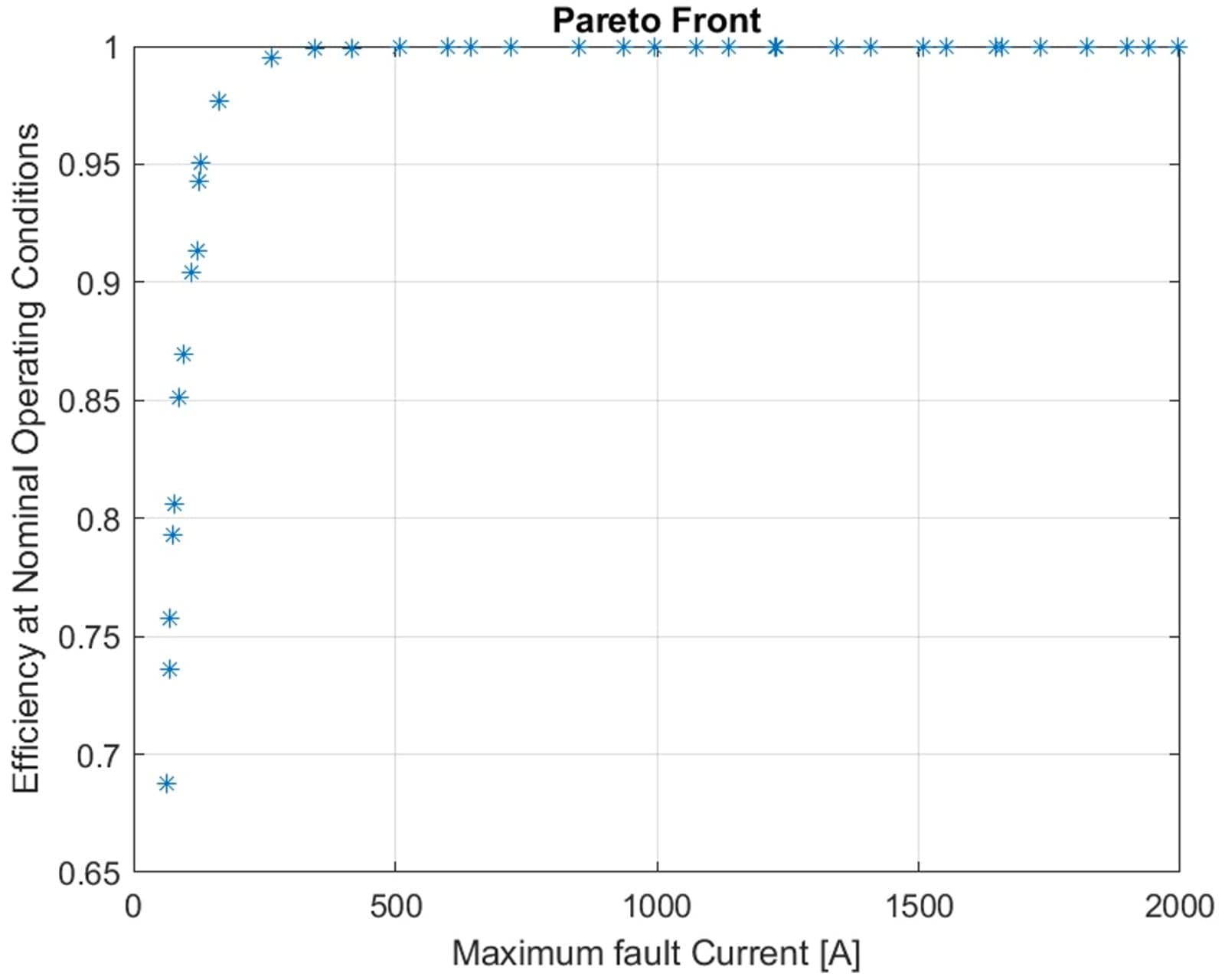
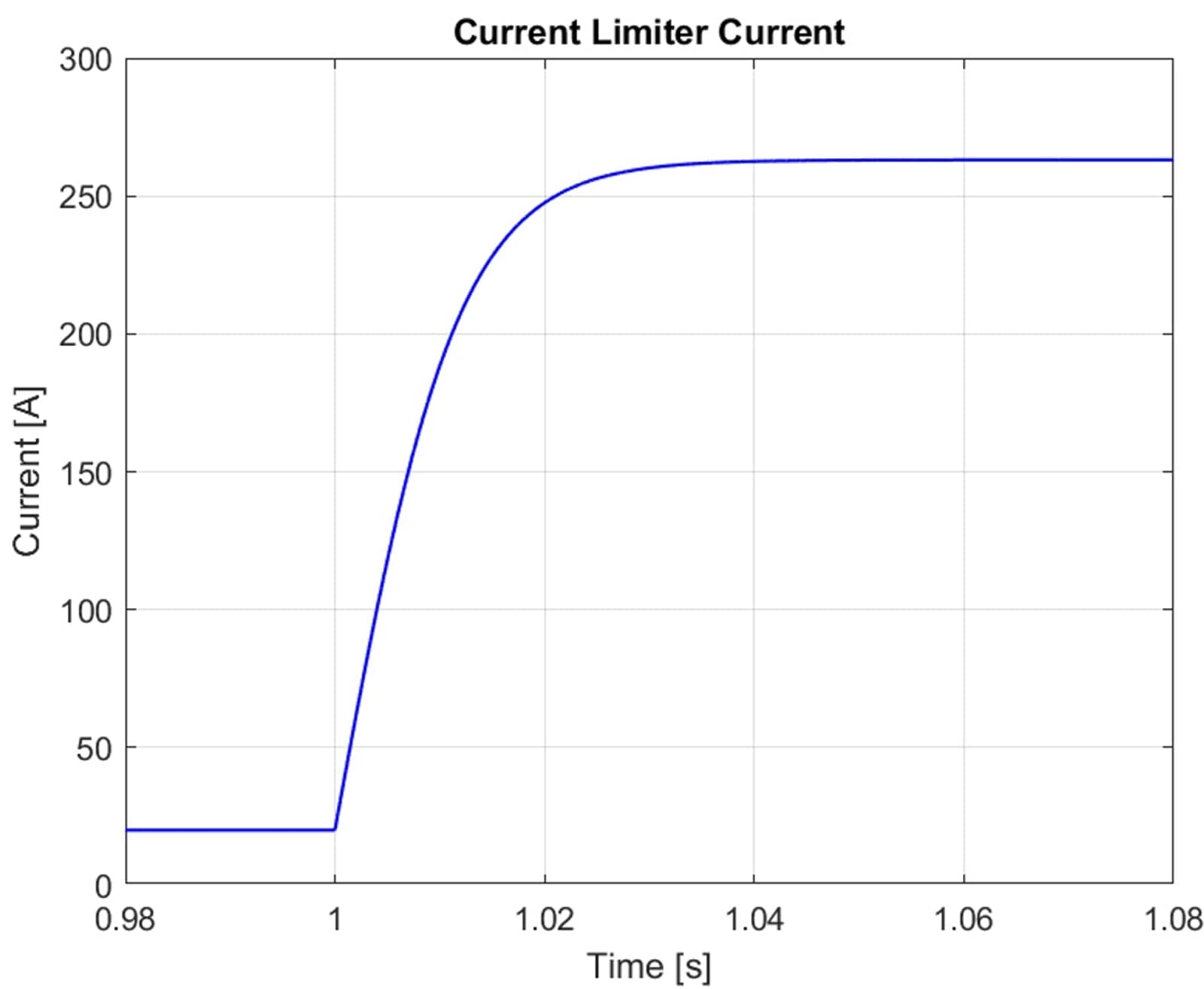
Following the calculation of the optimal points, a solution complying with the desired trade-offs was selected and ultimately simulated in SIMSCAPE, to validate that the current limiter exhibits the desired behaviour. For the presented example, the calculated solution is limiting the fault current at 264A, with an efficiency of 99.5%, values which were eventually validated in the simulation presented in Figure 3.
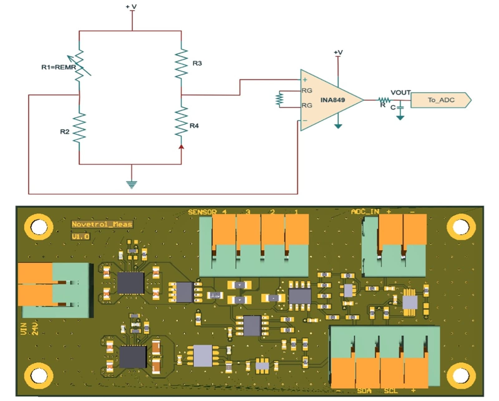
The EMR effect results in subtle changes in the device resistance, when it is exposed to variable magnetic fields. Capturing these small changes requires a precision measurement system, designed to maximise its performance.
A dedicated electronic board is the main component of this system (Figure 4). The proposed design provides a stable, controlled measurement system converting the EMR chip’s minute resistance changes into measurable differential voltage signals. These signals are then processed through a low noise differential amplification chain, which maintains a high common mode rejection, thus preparing the output for high resolution data acquisition.
Together, the EMR chip and measurement board are parts of a high fidelity sensing platform suitable for advanced energy applications, including magnetic field monitoring, equipment diagnostics and digitally enabled infrastructure, where precise and reliable sensing is essential.
Conclusion
The NOVETROL project demonstrates that extraordinary magnetoresistance (EMR) technology offers a promising pathway for safe, efficient, and scalable LVDC fault protection. It plans laboratory prototypes to validate the concept, while life cycle assessments ensure environmental and social sustainability.
An optimization methodology was developed, allowing the creation of optimised current limiter design for the targeted use case. This integrated approach aligns with European Green Deal objectives, enabling resilient, interoperable and future-proof LVDC infrastructures.
References
1. Solin, S. A.; Thio, T.; Hines, D. R.; Heremans, J. J. (2000). Enhanced Room-Temperature Geometric Magnetoresistance In Inhomogeneous Narrow-Gap Semiconductors. Science, 289(5484), 1530–1532. DOI: 10.1126/science.289.5484.1530.
2. Fotias, N.; Costea, S. D.; Enger, L. G.; Letang, J. (2025) A Multi-Objective Based Design Optimization Approach of Extraordinary Magnetoresistance Current Limiters, submitted to ACDC Europe 2026, 22nd IET International Conference on AC and DC Power Transmission, Berlin, April 2026
About the authors
Nikolaos Fotias is Lead Engineer in Power Electronics at Eaton’s European Innovation Centre in Prague. With nine years’ experience in automotive and industrial electronics, he specialises in designing advanced power converter topologies. Holding degrees from NTUA and UCL, he contributes to EU projects advancing safer, smarter energy systems.
Stefan Dan Costea is Senior Specialist Engineer at Eaton’s European Innovation Centre, driving innovation in energy automation and optimisation. With over 20 years of R&D experience, he has co-authored patents, led EU-funded projects and advanced sustainable power systems, shaping Europe’s transition toward smarter, cleaner energy solutions.
Samaneh Hesabirad is a Senior Engineer in Power Electronics at Eaton’s European Innovation Centre in Prague. She holds a Master’s in Electrical Engineering from Sapienza University, specialising in ultra-fast EV charging systems. With expertise in simulation and circuit design, she advances sustainable energy technologies for electric mobility.
Related tags
Most popular
Join the community for freeAnd get access to all content
Related projects

NOVETROL
+1
1 December 2024 - 30 November 2027
View project