A current limiter for safe LVDC implementation
Guest/partner contributor
Posted on: 12 June 2026
A compact and cost-effective current limiter for LVDC based on the extraordinary magnetoresistance effect is presented in the NOVETROL project.

As shown by numerous studies, fast and selective fault current limitation is a very important functional capability for low voltage DC (LVDC) systems, where the absence of natural current zero crossings leads to very steep fault current rise rates.
The fastest protection devices (solid state circuit breakers for DC) can be expensive. A more affordable option, therefore enabling the mass adoption of DC power systems, is the hybrid circuit breakers. However, these breakers are slower, and the fault current can reach dangerous levels before the breaker can react, unless current limiting measures are taken.
Current industrial practice relies on hybrid DC circuit breakers supported by series 'time buying' inductors or reactors, which slow the fault current evolution to enable timely detection, commutation, and interruption. While effective, these inductive solutions add volume, stored magnetic energy, and design constraints.
The NOVETROL project addresses this challenge by developing innovative current limiting devices. The concept operation was validated by the modeling and system‑level simulation of an extraordinary magnetoresistance (EMR)‑based current limiter, focusing on the current evolution during the limitation regime.
The results are quantitatively compared with conventional time‑buying inductor solutions used in hybrid DC circuit breakers.
NOVETROL methodology
The NOVETROL project aims at developing a smaller and cheaper current limiter devices, implementing a novel concept that takes advantage of the physical phenomena that occur when the current has the steep increase.
As described in [1][2], the first implementation, shown in figure 1, uses the main current to create the variable magnetic field that will trigger the increase of the resistance in the EMR.
The operation of the current limiter was validated by modelling and simulation and compared with the current solution operation of the same system with a time-buying inductor.
![Figure 1. EMR-based current limiter device [3].](/_next/image?url=https%3A%2F%2Fenlit.stream.prepr.io%2F9d1itqc1ub4%2Fw_1600%2Ffigura-1.png&w=3840&q=75)
The two main components of the device, the magnetic field generator and the EMR element, are modelled separately and as part of a system model. The optimum design is decided based on the mathematical description of the physical phenomena, using a multi-objective optimization methodology, as described in [3].
Summarising the approach from [3[, the mathematical description of the resistance of the EMR component was generated as a function of the excitation field, the material properties and the geometrical parameters of the components. The magnetic flux density was expressed as a function of the core parameters: geometry, material properties, the number of coil turns and the air gap geometry. These functions are further combined to compute the current limiter’s resistance. The geometrical/material properties form the design parameters of the current limiting device. The expression of the resistance, used in the modelling and simulation, is [4]:

where ρ0 is the resistivity of the material under no magnetic field, μmat is the carrier mobility of the material, B is the magnetic flux density, tEMR is the thickness and lEMR is the length of the EMR chip, and SEMR is the cross-section area of the conduction path in the EMR chip.
The magnetic flux density was modelled as function of the main current I and the parameters of the magnetic field generator as [4]:

where N is the number of coil turns, and lgap is the total air gap length in the magnetic generator core.
Using the two equation, the dependence of the EMR resistance to the main current was implemented in a Simulink block, modeling the EMR element.
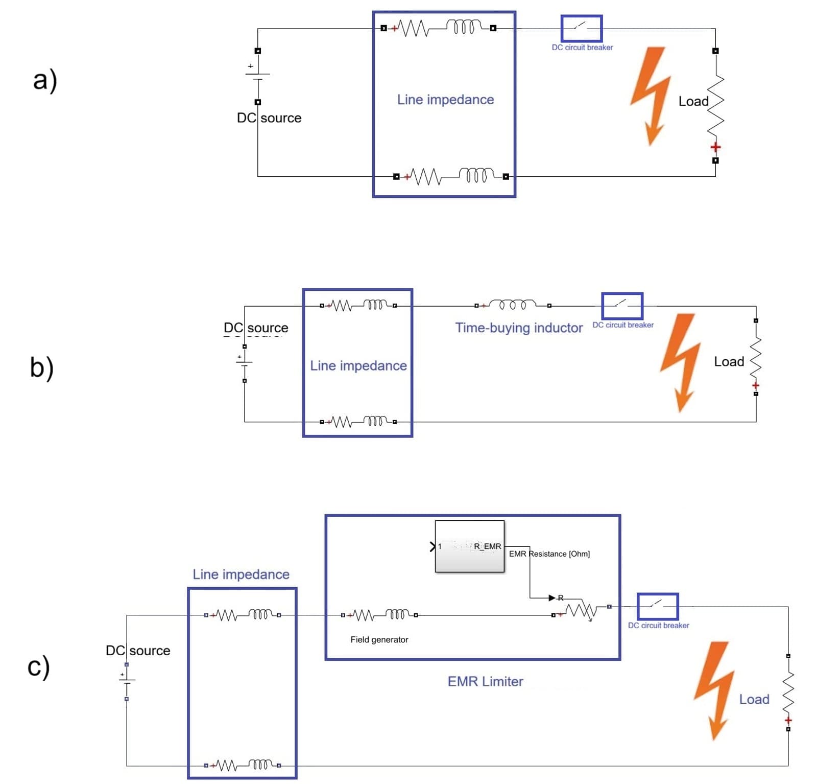
The concept was virtually validated in Simulink, by simulating the operation of a simple DC circuit (700V DC voltage source, 3.5Ω load, resulting in a 200A nominal current). The simulation was run for three topologies, with no current limiter, with a time buying inductor and with the EMR limiter (Figures 2a-c).
Results and discussion
The time evolution of the main current in the three situations is presented in figure 3. A short circuit was imposed at t=1ms, and it was assumed that the circuit breaker can interrupt the circuit after the 650µs after fault detection (at about 20µs after the fault) [5][6]. The average line impedance is modelled as a series RL element for each branch (50mΩ, 15µH) [5].
It can be seen that without imposed limitations, the fault current can reach 6kA. This current creates a very high risk for equipment and humans. Unless a suitable limiter is used, the whole circuit has to be oversized, including wire gauge and converter current capabilities. This approach greatly increases the cost, a deterrent in the adoption of DC technology.
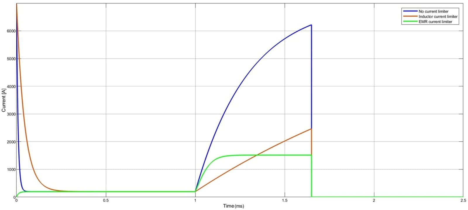
If included, the time-buying inductor limits the rate of increase of the fault current. In this way, when the circuit breaker interrupts the circuit, the current can be managed by the circuit, without high equipment costs. If a 130µH inductor is used [5], the rate is 5A/µs, and the current reaches about 2.7kA in 650µs. While this solution is often used with hybrid DC circuit breakers, it includes bulky and expensive air inductors. Also, the maximum value of the current will vary with the breaker reaction time.
Finally, in the EMR current limiter there are two competing effects. On one hand, the increase in the main current triggers an increase in the magnetic flux density, resulting in an increase of the series resistance of the EMR element. On the other hand, an increased resistance will lower the main current as targeted, but it is followed by a decrease in the magnetic flux density, and in the resistance of the EMR element.
The two opposing effects operate simultaneously, reaching an equilibrium. In figure 3 c), a stable value of the limited current is seen at 1.5kA, lower than the maximum value reached with the time buying inductor. In this case, the current could be maintained at this manageable value, even if the circuit breaker does not have a predictable behaviour. The main limitation in this situation is given by the circuit capability to withstand the stable value of the current.
Conclusion
An EMR-based current limiter for LVDC systems has been presented and evaluated through modelling and simulation. The device provides passive, self-regulating fault current limitation without bulky inductors. Results demonstrate stable and reduced fault currents with less dependency on circuit breaker reaction time.
The concept is therefore promising for compact and cost-effective LVDC protection, with future work focusing on experimental validation and thermal performance assessment.
References
- Novel LVDC implementation with current limiter based on extraordinary magnetoresistance
- P. Kopejtko, Current controlling element based on saturation of a magnetic circuit, European Patent EP 3961925 A1, published Feb. 16, 2022.
- Solin, S. A., Thio, T., Hines, D. R. & Heremans, J. J., 2000. Enhanced Room-Temperature Geometric Magnetoresistance In Inhomogeneous Narrow-Gap Semiconductors. Science, 289(5484), 1530–1532.
- Fotias, N., Costea, S. D., Enger, L. G. & Letang, J., 2025. A Multi-Objective Based Design Optimization Approach of Extraordinary Magnetoresistance Current Limiters. Submitted to 2026 IEEE 8th International Conference on DC Microgrids (ICDCM), Xi'an (China), June 2026
- Askan, K. & Schasfoort, P., 2021. Variable Voltage IGBT Gate Driver for Low Voltage Hybrid Circuit Breaker. IEEE Fourth International Conference on DC Microgrids (ICDCM), Arlington, VA, USA, pp. 1-7.
- Askan, K., & Klof, R., 2024. Passive Methods Limiting Leakage Current in Metal-Oxide Varistor Used as Voltage Clamping Circuit. Low Voltage DC Semiconductor Circuit-Breakers, PCIM Europe, Nuremberg, Germany, pp. 1540-1549.
About the authors
Yagmur Hazman is an Engineer in Power Electronics at Eaton’s European Innovation Centre in Prague. Holding Bachelor of Aerospace Engineering from METU and a Master’s Degree in Aerospace Technologies from BUT, she contributes to energy transition and clean aerospace projects by performing thermal, electromagnetic and electro-thermal modelling of physical systems.
Nikolaos Fotias is a Lead Engineer in Power Electronics at Eaton’s European Innovation Centre in Prague. With nine years’ experience in automotive and industrial electronics, he specialises in designing advanced power converter topologies. Holding degrees from NTUA and UCL, he contributes to EU projects advancing safer, smarter energy systems.
Stefan Dan Costea is a Senior Specialist Engineer at Eaton’s European Innovation Centre, driving innovation in energy automation and optimisation. With over 20 years of R&D experience, he has co-authored patents, led EU-funded projects and advanced sustainable power systems, shaping Europe’s transition toward smarter, cleaner energy solutions.
Samaneh Hesabirad is a Senior Engineer in Power Electronics at Eaton’s European Innovation Centre in Prague. She holds a Master’s Degree in Electrical Engineering from Sapienza University specialised in ultra-fast EV charging systems. With expertise in simulation and circuit design, she advances sustainable energy technologies for electric mobility.
Related tags
Most popular
Join the community for freeAnd get access to all content
Related companies
EATON
Related projects

NOVETROL
+1
1 December 2024 - 30 November 2027
View project