Novel current control for climate neutral energy infrastructure in NOVETROL
Guest/partner contributor
Posted on: 21 April 2026
This article presents the design methodology and results of a custom 20A/200A magnetic field generator, engineered for fast response in power electronic systems.

Achieving the EU’s climate neutrality ambitions requires a next generation of power electronics capable of reliable, fast and efficient operation in the new energy generation and distribution environment.
As part of the EU funded NOVETROL project, the Eaton ERL team in Prague is developing new current control and limitation techniques to enhance monitoring, protection and dynamic regulation of high current systems. In our previous contribution [1], we have described the current limiting concept, which integrates the variable extraordinary magnetoresistance (EMR) element with a magnetic field generator.
In this contribution, we are presenting the steps followed during the design of the magnetic field generator.
NOVETROL methodology
For the concept described in [1], the magnetic field generator is placed in line with the main current, thus triggering the increase in the resistance of the EMR element, in case of a short circuit or fast rise of the current from any cause. Therefore, for normal operation, the field generator should introduce a very low inherent resistance, and it should keep the magnetic field low enough (i.e. 0.1T), such that the EMR element is also maintained at a low resistance value.
In addition, for the current limiting operation, the magnetic field in the air gap of the generator should reach a value that is high enough (i.e. 1T) such that the EMR resistance can efficiently limit the current. As a constraint, the inductance L, which is also placed in series with the main current, has to be kept low enough such that it does not introduce unwanted delays in current dynamics, preventing the current limiter from operating efficiently.
We used as a first example a system with 20A maximum operating current, and we employed classical electromagnetic theory with modern CAD driven simulation. Starting with required field conditions – 0.1T at 20A and 1T at 264A (as the designed limited current value, as presented in [1]) – the team defined constraints governing inductance, airgap behaviour and winding/core parameters (number of turns N, cross section area for the core A).
Magnetic circuit fundamentals
The design starts from the standard relationships [2] between magnetic flux (Φ), flux density (B), magnetomotive force (N·I) and circuit reluctance (Rm) for the device shown in Figure 1 below:
B = Φ/A (1)
Φ = N·I/Rm (2)
Rm = l/μ0μrA for core and gap segments (3)
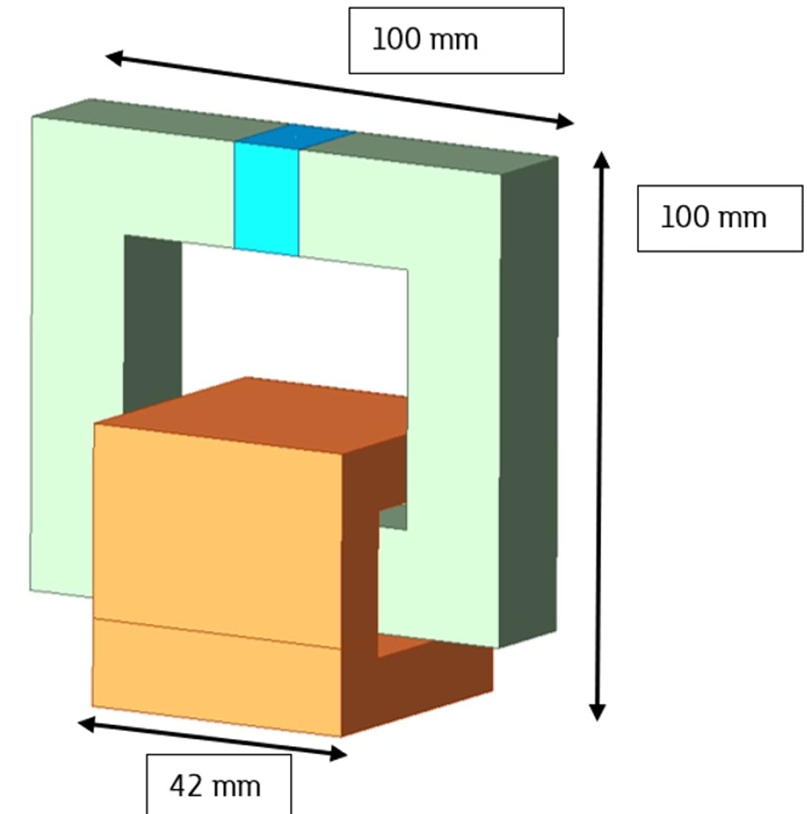
The air gap (shown in light blue) is designed to prevent core saturation at currents up to 264A, which is the calculated optimised value of the limited current. With the air‑gap reluctance dominating, the target magnetic flux density in the gap can be expressed as:
Bgap = N·Iμ0/lgap (4)
The inductance constraint (L≤20µH) is used to determine the optimal turns count and air gap length:
L = N²μ0A/lgap (5)
Design parameters
Using a core/air gap area of 0.016×0.016m² and a gap length of 11mm, the resulting working design parameters are N=50 turns and L=20µH at 20A (as targeted).
These parameters ensure rapid magnetic response without limiting the control system’s reaction time – critical for grid supporting devices.
CAD and simulation workflow
Once theoretical values were validated, the design was built in ANSYS Maxwell, enabling both magnetostatic analysis and validation of field distributions across the full current range. The CAD model defines coil geometry, core dimensions and air gap placement as in Figure 1, forming the foundation for simulation driven optimisation.
Results and discussion
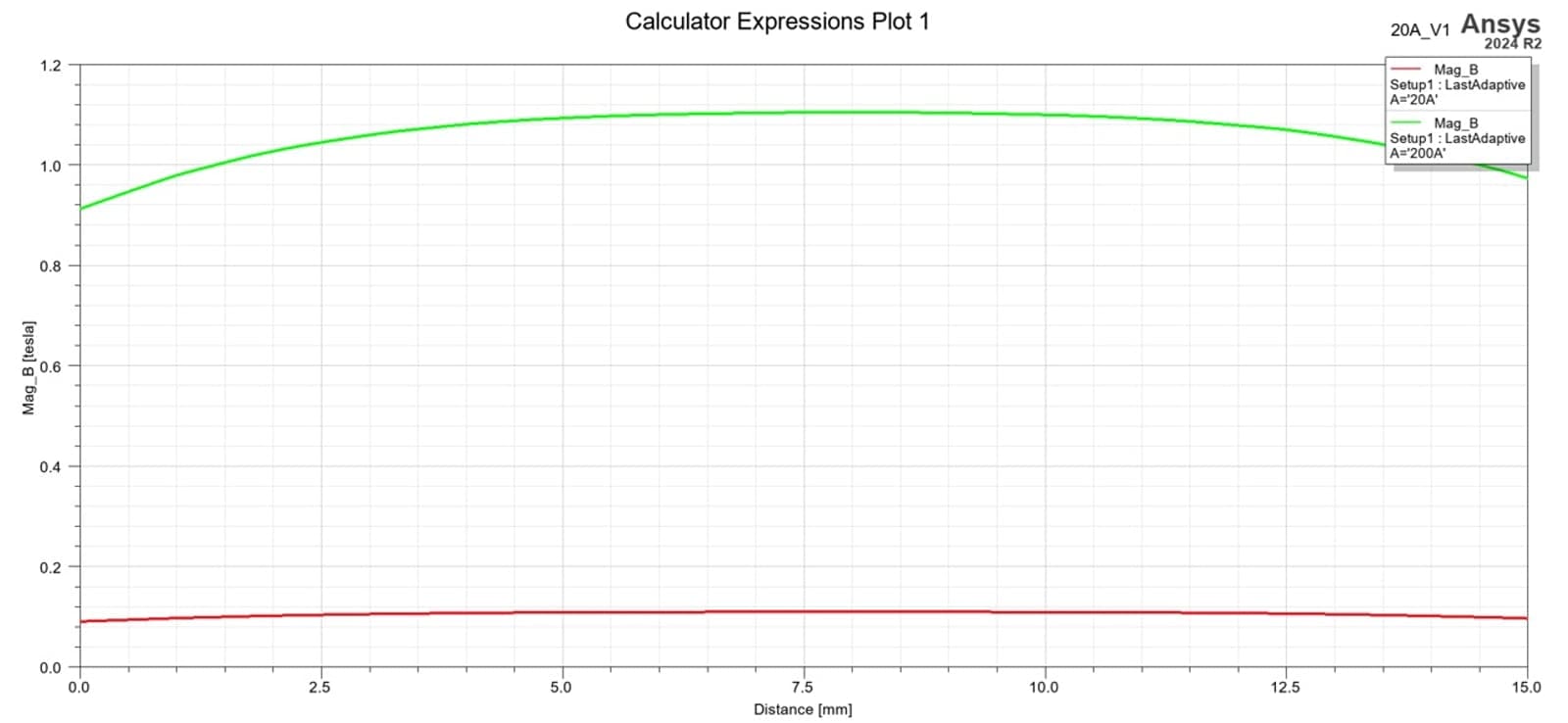
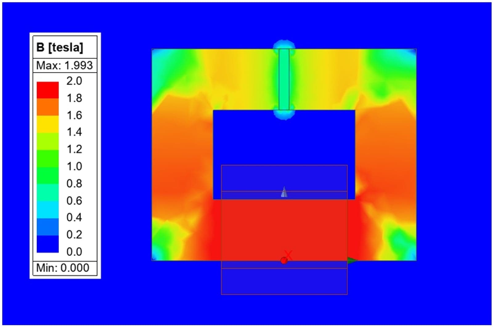
The simulation produced detailed flux density maps and contour plots that confirm the concept’s feasibility, as shown in Figure 2.
Field behaviour at operating current and during current limiting
Simulated results (Figure 2) show:
- 0.1T achieved in the air gap at nominal 20A current;
- 1T achieved at 264A peak current.
These values closely match the design targets, validating the analytical calculations.
The field contour plots (Figure 3) demonstrate uniform flux density across the centre region of the air gap under both operating points, ensuring predictable sensor behaviour and stable calibration.
These results provide an initial validation of the concept and will be verified in a hardware prototype that is under development.
Impact on energy sector applications
We have shown that a magnetic field generator can be designed according to the requirements of the application. A reliable and tunable magnetic field generator enables:
- Accurate current limiter development;
- Fast transient reaction for efficient protective electronics;
- Improved stability modeling for next generation grid converters;
- Enhanced laboratory validation for EU mandated grid compatibility.
By aiming for low inductance, the NOVETROL generator ensures that rapid changes in current can be detected and mitigated – a crucial capability for high renewable grid scenarios where volatility is common.
Conclusion
The NOVETROL magnetic field generator exemplifies how disciplined electromagnetic design, supported by robust simulation tools, can produce precise and high performance devices for future energy infrastructure. Delivering accurate field generation at both nominal and fault mitigation operating points, the design supports advanced power control and management, essential for modern power systems.
To learn more about the project’s ongoing research outputs, visit the NOVETROL project website or contact Eaton ERL Prague.
References
1. Novel LVDC implementation with current limiter based on extraordinary magnetoresistance.
2. Chapman, S. J., 2011. Electric Machinery Fundamentals, 5th ed. New York, NY, USA: McGraw‑Hill.
About the authors
Yagmur Hazman is an Engineer in Power Electronics at Eaton’s European Innovation Centre in Prague. Holding a Bachelor of Aerospace Engineering from METU and a Master’s in Aerospace Technologies from BUT, she contributes to energy transition and clean aerospace projects by performing thermal, electromagnetic and electro-thermal modelling of physical systems
Nikolaos Fotias is a lead engineer in power electronics at Eaton’s European Innovation Centre. With nine years’ experience in automotive and industrial electronics, he specialises in designing advanced power converter topologies. Holding degrees from NTUA and UCL, he contributes to EU projects advancing safer, smarter energy systems.
Stefan Dan Costea is Senior Specialist Engineer at Eaton’s European Innovation Centre, driving innovation in energy automation and optimisation. With over 20 years of R&D experience, he has co-authored patents, led EU-funded projects and advanced sustainable power systems, shaping Europe’s transition toward smarter, cleaner energy solutions.
Samaneh Hesabirad is a senior engineer in power electronics at Eaton’s European Innovation Centre. She holds a Master’s in Electrical Engineering from Sapienza University, specialising in ultra-fast EV charging systems. With expertise in simulation and circuit design, she advances sustainable energy technologies for electric mobility.
Related tags
Most popular
Join the community for freeAnd get access to all content
Related projects

NOVETROL
+1
1 December 2024 - 30 November 2027
View project